

To make the value 0 is easy - the data input is just set to 0v. But clocking in this value is harder : 8 pulses must occur on the gamelink clock line for every MIDI clock signal. This is the job of the interface.
The code for a MIDI clock signal is "11111000" this is sent down the MIDI cable with a start and stop bit, making the overall MIDI code: "1111110000". The normal state of a MIDI line is 1, so during a MIDI clock signal the MIDI line drops from 1 to 0 for 4 bit periods. The MIDI system has a bit rate of 31250bps - so the line goes low for 128us during a MIDI clock signal.
Using this property of the MIDI signal it is arranged that gamelink clock pulses are sent whenever the MIDI signal is zero. The rate of this clock is set to 62500Hz, so that 8 pulses occur for each MIDI clock signal. The means that the required $00 byte is clocked in for each MIDI clock.
The 62500Hz signal is generated by passing a 1MHz signal through a divide-by-16 counter. The 1MHz is made from a easily obtainable crystal oscillator.
Lastly, to prevent ground loops, the MIDI signal must pass through an optoisolator. This is part of the MIDI standard, and so is no big shits. Except the optoisolator has been arranged to invert the MIDI data, which matches the enabling signal for the divide-by-16 counter.
 |
 |
 |
||||
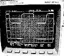
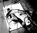
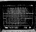
| The proof 1: incoming MIDI clock pulses(top) generate LSdj signals(bottom) | The interface under development | The proof 2: incoming MIDI clock pulses(bottom) generate LSdj signals(top) |